SRC59
Current Shunt Resistors
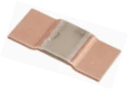
SRC59 Series Current Shunt Resistors aid precision measurement and high-current applications. A wide range of precision shunts,designed for use with kilowatt-hour meters and other high-current applications where a high level of accuracy is required, is now available from PROSEMI.
Features
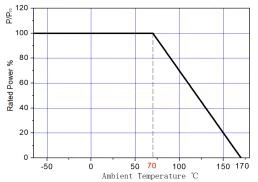
- Power rating up to 15 W at 70°C
- Excellent long term stability
- Extremely low resistance values (down to 0.2mΩ)
- Halogen free, lead free and RoHS compliant
Appications
- Power modules
- Frequency converters
- Current sensor for power hybrid sources
- High current for automotive
- Lithium battery protection board
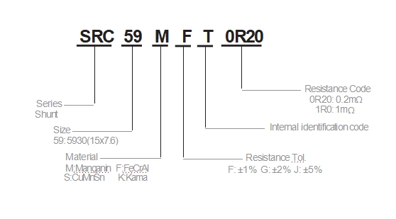
| Part Number | Power Rating P70°C (W) | Resistance Range (mΩ) | TCR (ppm/°C) | Material |
|---|---|---|---|---|
| SRC59F/K_T3R0 | 7 | 3 | ±50 | FeCrAl/Kama |
| SRC59F/K_T2R0 | 7 | 2 | ±50 | FeCrAl/Kama |
| SRC59F/K_T2R0 | 8 | 1.5 | ±50 | FeCrAl/Kama |
| SRC59F/K_T1R0 | 9 | 1 | ±50 | FeCrAl/Kama |
| SRC59M_T0R75 | 10 | 0.75 | ±75 | Manganin |
| SRC59M_T0R50 | 10 | 0.5 | ±75 | Manganin |
| SRC59M_T0R30 | 10 | 0.3 | ±100 | Manganin |
| SRC59M_T0R20 | 15 | 0.2 | ±100 | Manganin |
| SRC59S_T0R10 | 15 | 0.1 | ±200 | CuMnSn |
- Applicable temperature range of -55°C to +170°C
- Power rating is guaranteed for use an aluminum substrate (MCPCB) Part
- Number definition “_ ” of Resistance Tolerance
Dimension
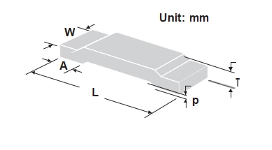
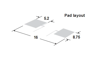
| Type | L (mm) | W (mm) | T (mm) | A (mm) | p (mm) | Quantity |
|---|---|---|---|---|---|---|
| SRC59F_T3R0 | 15±0.3 | 7.6±0.4 | 0.79±0.2 | 4.2±0.3 | 0.5±0.1 | 2000 |
| SRC59F_T2R0 | 15±0.3 | 7.6±0.4 | 0.90±0.2 | 4.2±0.3 | 0.5±0.1 | 2000 |
| SRC59M_T1R5 | 15±0.3 | 7.6±0.4 | 1.11±0.2 | 4.2±0.3 | 0.5±0.1 | 2000 |
| SRC59F_T1R0 | 15±0.3 | 7.6±0.4 | 1.36±0.2 | 4.2±0.3 | 0.5±0.1 | 2000 |
| SRC59M_T0R75 | 15±0.3 | 7.6±0.4 | 0.91±0.2 | 4.2±0.3 | 0.5±0.1 | 2000 |
| SRC59M_T0R50 | 15±0.3 | 7.6±0.4 | 1.10±0.2 | 4.2±0.3 | 0.5±0.1 | 2000 |
| SRC59M_T0R30 | 15±0.3 | 7.6±0.4 | 1.48±0.2 | 4.2±0.3 | 0.5±0.1 | 2000 |
| SRC59M_T0R20 | 15±0.3 | 7.6±0.4 | 2.00±0.2 | 4.2±0.3 | 0.5±0.1 | 1500 |
| SRC59S_T0R10 | 15±0.3 | 7.6±0.4 | 2.5±0.2 | 4.2±0.3 | 0.5±0.1 | 1000 |
Storage Conditions
- Temperature: 22~28°C , Humidity: 40~75%
Power Derating Curve
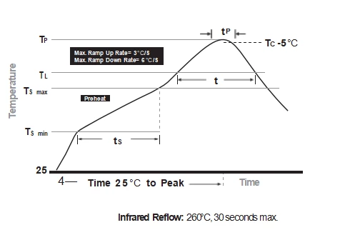
Soldering Parameters
| Parameter | Value |
|---|---|
| Temperature min (Tsmin) | 150°C |
| Temperature max (Tsmax) | 200°C |
| Time (Tsmin to Tsmax) (ts) | 60 - 120 seconds |
| Average ramp-up rate (Tsmax to Tp) | 3°C/second max |
| Liquidous temperature (TL) | 217°C |
| Time at liquidous (tL) | 60 - 150 seconds |
| Peak temperature (Tp) | 260+0/-5°C |
| Time within 5°C of actual peak Temperature (tp) | 10 – 30 seconds |
| Average ramp-down rate (Tp to Tsmax) | 6°C/second max |
| Time 25°C to peak temperature | 8 minutes max |
Endurance Test
| Iterms | Additional Requirements | Reference | Limits | |
|---|---|---|---|---|
| Temperature Cycling | 1000 Cycles(-55℃ to +125℃) Measurement at 24±2 hours aftertest conclusion | JESD22 MethodJA-104 | ±0.5% | |
| High Temperature Exposure | 1000hrs.@T=125℃.Unpowered. Measurement at 24±2 hours aftertest conclusion | MIL-STD-202 Method 108 | ±0.5% | |
| Moisture Resistance | t=24hrs/cycle.Note:Steps 7a & 7b not required. Unpowered. | MIL-STD-202 Method 106 | ±0.5% | |
| Biased Humidity | 1000hrs 85℃/85%RH 。Note: Specified conditions: 10% of operating power. Measurement at 24±2 hours after test conclusion | MIL-STD-202 Method 103 | ±0.5% | |
| Operational Life | Condition D Steady State TA=125℃ at rated power. Measurement at 24±2hours after test conclusion | MIL-STD-202 Method 108 | ±0.5% | |
| Solderability | 245℃±5℃,5s+0.5s/-0 | J-STD-002C | 95% Coverage Min | |
| Vibration | 5 g's for 20 min, 12 cycles each of 3 orientations. Note: Use 8"X5" PCB .031"thick 7 secure points on one long side and 2 secure points at corners of opposite sides. Parts mounted within 2" from any secure point. Test from10-2000Hz. Measurement at 24±2 hours after test conclusion | MIL-STD-202 Method 204 | ±0.5% | |
| Resistance to Soldering Heat | 260℃±5℃ , 10s±1s Measurem ent at 24±2 hours after test conclusion | MIL-STD-202 Method 210 | ±0.5% | |
| Short Time Overload | 5×Rated power for5 s Measurement at 24±2 hours after test conclusion | MIL-STD-202 Method 301 | ±0.5% | |